Stop, Go Lights
I made this up on a rainy Sunday afternoon. I had the parts left over, so it didn't cost anything. If you had to buy the parts it would cost about $20 to make.
If you go to the link below it will show you how it works.http://www.youtube.com/watch?v=gEhmwGFMvko
A quick disclaimer. Everything works off 12v or less, but I am not a electronics expert, so if it burns down your house etc, don’t blame me.
The LED’s only need about 5 volts to work, so I just used a 9v transformer I had lying around. Jaycar will sell you the LED’s and resistors etc.
This project provides stop and go lights in red and green for tracks which have track power controlled by a relay (such as when using Trackmate).
It should also work with a digital track which has DC power feed to the track, as this can also be used to trigger the relay, thus switching which colour of LEDs is lit.
You will need
- Bread Board
- LED lights
- Resistors x2
- Double throw relay (5 pin)
- A 6-12v power supply (optional)
- Wire

First off decide how you want to arrange your lights. I wanted 2 rows of 5 lights each for red and green. Cut the bread board to suit. If you want a boarder around them, make sure you allow for this when you cut it. Put the LED’s though the holes with the neg side (shorter) to the left (as viewed from the back). I used a bit of super glue to hold them in place (on the front). Then trim the wire off the LED so about 0.5mm is left, except for the top 2 middle ones and the left bottom (neg) and the right bottom (pos).

Solder them all in place (make sure the solder doesn’t jump across) and then cross the 2 top ones together (left light pos/right light neg) and solder them. Cut a divider in the copper strip in the bread broad and repeat for the lower half of the lights.

Now join the 2 left hand wires (top and bottom neg) together and solder on some wire (I prefer black). (If the top lights are red), solder on some red wire to the right hand top wire and some green wire to the bottom right hand wire. Cover the exposed wire with heat shrink or some insulation tap. You will need to add a resistor to each of these 2 wires. This can be done anywhere before the power supply. Do not cover the resistors up, as they get hot. The type of resistor will depend the type/number of LED’s and the voltage of the power supply. You can use the track supply the run the LED’s, but I prefer to use a separate supply.

To wire this up to a relay you will need a one with 5 pins. (double throw). The negative power supply from the track goes to pin 1 and the pos to pin 2. The common negative from the lights gets wired straight to the negative of the separate power supply for these LEDs, while the positive from the power supply gets wired to pin 3. The red positive wire from the lights gets wired to pin 4 and the green positive wire from the lights gets wired to pin 5.
SO; when the track power is "off" before the start of a race, the red lights will be lit. When track power is turned on, it also triggers the relay, so power to the Red LEDs is cut, but the Green LED's now get a positive feed through the relay and will be lit. When track power is cut - - - you're back to the red LEDs.
I find that unless a tool has a home close by then it tends to get left on the bench. Likewise, if it's difficult to store. Pliers and cutters are like this. They are normally stored upside down and waggle about in a slot. How about this?
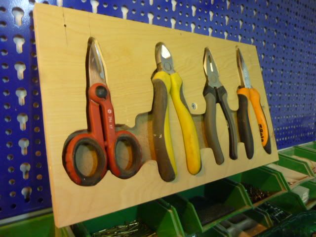
Simply draw round your tools, cut out with a jigsaw or bandsaw leaving space for your fingers to lift out the tools, slap a bit of ply or hardboard on the back and a strip of wood along the bottom, add two round head screws to the top and hang on your pegboard.
Tool Storage Idea's
Another small project, thanks to Graham Lane for this one.I find that unless a tool has a home close by then it tends to get left on the bench. Likewise, if it's difficult to store. Pliers and cutters are like this. They are normally stored upside down and waggle about in a slot. How about this?
Simply draw round your tools, cut out with a jigsaw or bandsaw leaving space for your fingers to lift out the tools, slap a bit of ply or hardboard on the back and a strip of wood along the bottom, add two round head screws to the top and hang on your pegboard.